Iranian Classification Society Rules

< Previous | Contents | Next >
Section 22 Cable Laying
2201. Application
The requirements in this Section apply to tests and inspection for the approval of fire stop method for bunched cables (ex: fire stop mat, hereinafter referred to fire stop methods in this Section)
and nonmetallic cable
with the requirements
bands which are required an advance approval by the Society in accordance
in Pt 6, Ch 1, 109. and 407. 4 of the Rules for Classification of Steel
Ships, Pt 6, Ch 1, 404. 1 and of Steel Ships.
407. 1 of the Guidance relating to the Rules for the Classification
2202. Data to be submitted
The manufacturer or constructer is to submit to the Society the drawings and documents specified in (1) for the approval of the fire stop methods, and those specified in (2) for the approval of nonmetallic cable bands in addition to those specified in 102.
(1) Fire stop methods of cable
(A) Characteristic of materials
(B) Instructions for work procedures (in case of paints being used, the painting method and pro- cedure including painting condition and the dry film thickness of paint are to be specified)
(C) Copies of certificates or test records issued by official organizations (if any)
(2) Nonmetallic cable bands
(A) Type name
(B) Construction plan (including principal dimensions)
(C) Characteristic of materials
(D) Copies of certificates or test records issued by official organizations (if any)
2203. Type tests
1. Prevention methods of flame spread through cable
The type tests for prevention methods of flame spread through cable are to be carried out in ac- cordance with KS C IEC 60332-3-22.
2. Nonmetallic cable bands
The type tests for nonmetallic cable bands are, according to the purpose and kind, out in accordance with the requirements given in Table 3.22.1.
to be carried
Table 3.22.1 Approval test method and acceptance criteria for non-metallic cable bands
Kind | Test item | Approval test method and acceptance criteria |
Test specimens | The tests are to be done with the ten test specimens which were left in air for 30 minutes prior to tests, after conditioned at 20 ± 2°C and 50 ± 2% relative humidity for 24 hours. | |
Test method | Flame retardant test | (a) The test specimens are to be set upright in a test box of 1,200 ± 25 mm high, 300 ± 25 mm wide, 450 ± 25 mm deep, opened front face, nonmetallic bottom and other faces made of wire net and the distance from the lowest side of specimens to the bottom is to be adjusted to 50 mm. (b) The heating source from gas burner with tip of inner diameter 10 mm is to be blue flame of length of 100 mm and temperature of 800 ± 50°C. (c) The bottom of burner is to be at an angle of 45° against the specimens and the flame cen- ter is to be positioned at the height of 50 mm above the lowest side of specimen. The flame is to be applied for 60 seconds. (d) When the flame is removed, the flame ignited on the specimen is to be self-extinguished and the burnt trace is not to reach to the top of upper part as cleaned. |
Guidance for Approval of Manufacturing Process and Type Approval, Etc. 2015 135
![]()
![]()
Table 3.22.1 Approval test method and acceptance criteria for non-metallic cable bands (continued)
Kind | Test item | Approval test method and acceptance criteria |
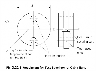
Test method | Mechanical property test before and after aging test | (a) The tensile strength for ten test specimens is to be measured using the jig shown in Fig 3.22.3 before and after the aging test. The length of A described in the Fig is 30 mm for specimens of 200 mm length or less, and is chosen as appropriate for those of more than 200 mm length.
(b) The test specimens are to be placed at a temperature of 90 ± 2°C for 240 hours. (c) The required tensile strength before and after aging test is shown in Table below. |
Bending test of low temperature | (a) Effective length of specimen except securing part and end is to be tested. (b) After the aging test in (b) of Mechanical property test before and after aging test above, the diameter of round bar which is not more than 5 times of thickness of test specimens and specimens are to be placed at temperature of - 25 ± 2°C for four hours, and the test specimens are spirally rolled on the bar 5 times at the speed of one revolution per 5 seconds. (c) When the test specimens rolled on the round bar are placed at room temperature, any crack is not to be allowed. |
Length of test specimen (mm) | Min. tensile strength (N) | |
before aging test | after aging test | |
200 or below | 250 | 188 |
over 200 | 500 | 375 |
3. Nonmetallic cable trays/protective casings
The type tests for cable trays/protective casings made of plastics materials are, according to the purpose and kind, to be carried out in accordance with the requirements given in Table 3.22.2.
Table 3.22.2 type tests for cable trays/protective casings made of plastics materials
Test item | Approval test method and acceptance criteria |
Impact Resistance Test | The test should be performed according to IEC 60082-2 using the pendulum hammer. (a) The test should be carried out on samples of cable tray lengths or cable ladder lengths of 250 mm ± 5 mm long. Samples of ladder should consist of two side-members with one rung positioned centrally. Samples of mesh trays should be prepared in such a way that there will be a wire in the centre. (b) Before the test, plastics components should be aged at a temperature of 90℃ ± 2℃ for 240 h continuously. (c) The samples should be mounted on wooden fibreboard of thickness 20 mm ± 2 mm. |
136 Guidance for Approval of Manufacturing Process and Type Approval, Etc. 2015
![]()
![]()
Approximate energy(J) | Mass of hammer (kg) | Fall height(mm) |
10 | 5.0 | 200 ± 2 |
Table 3.22.2 type tests for cable trays/protective casings made of plastics materials (continued)
Test item | Approval test method and acceptance criteria | |
Impact Resistance Test | (d) The samples to be tested should be placed in a refrigerator, the temperature within which is maintained at the declared temperature below with a tolerance of ±2℃. -25℃ to 90℃ for outdoor use + 5℃ to 90℃ for indoor use. Consideration will be given to the use of plastics cable trays/protective casings in the cold environment where the ambient temperature is below -25℃ provided the mechanical prop- erties of the plastics can be maintained for the intended purpose and the installation location. In this particular instance, the cold bend and cold impact properties of the materi- al should also be considered. (e) After 2 h, the samples should, in turn, be removed from the refrigerator and immediately placed in the test apparatus. (f) At 10 ± 1 after removal of each sample from the refrigerator the hammer should be allowed to fall with impact energy, mass of the hammer and fall height as belows: (g) The impact should be applied to the base, or the rung, in the first sample, to one of the side members in the second sample, and to the other side member in the third sample. In each case, the impact should be applied to the centre of the face being tested. (h) After the test, the samples should show no signs of disintegration and/or deformation that will impair the safety. | |
Safe Working Load (SWL) Test | application | Tests should be carried out for the smallest and largest sizes of cable trays lengths or cable ladder lengths, having the same material, joint and topological shape. |
Test tem- perature | Cable trays/protective casings and joints should be tested at the declared temperatures according to (d) of impact resistance test above. Alternatively, tests can be carried out: (a) at any temperature within the declared range if documentation is available which states that the relevant structural properties of the materials as used within the system do not differ by more than 5% of the average between the maximum and minimum property values, or, (b) only at maximum temperature within the range, if documentation is available, which states that the relevant structural properties of the materials, as used within the system decrease when the tempera ture is increasing, or (c) at maximum and minimum temperature only. | |
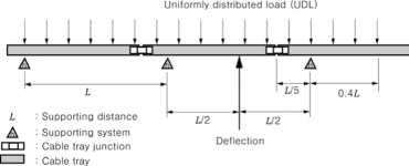
Test loads | All loads should be uniformly distributed (UDL) over the length and width of the samples as shown in Fig 3.22.4. The loads should be applied in such a way that a UDL is ensured even in the case of extreme deformation of the samples.
Fig 3.22.4 UDL applying method | |
Guidance for Approval of Manufacturing Process and Type Approval, Etc. 2015 137
![]()
![]()
Table 3.22.2 type tests for cable trays/protective casings made of plastics materials (continued)
Test item | Approval test method and acceptance criteria | |
Safe Working Load (SWL) Test | Load test | (a) To allow for settlement of the samples, a pre-load of 10% of the test load unless otherwise specified, should be applied and held for at least 5 min, after which the measurement appa- ratus should be calibrated to zero. (b) The load should then be gradually increased evenly longitudinally and transversely up to the test load continuously or when a continuous increase is impractical, the load may be in- creased by increments. These increments should not exceed about a quarter of the safe working load. The load increments should be distributed through the load plates longitudi- nally and transversely as evenly as is practical. (c) After loading, the deflection should be measured at the points specified to give a practical mid-span deflection.(refer to Fig 3.22.4) The samples should be left and the deflections measured every 5 minutes until the difference between two consecutive sets of readings is less than 2 % with regard to the first set of the two consecutive sets of readings. The first set of readings measured at this point is the set of deflections measured at the test load. (d) The maximum deflection should not exceed L/100 where L is the distance between the supports. (refer to Fig 3.22.4) (e) When subject to the test load the samples, their joints and internal fixing devices, should show no damage or crack visible to normal view or corrected vision without magnification. |
Breaking test | (a) The load should then be increased to l.7 times the test load. (b) The samples should be left and the deflections measured every 5 min until the difference between two consecutive sets of readings is less than 2 % with regard to the first set of the two consecutive sets of readings.(refer to Fig 3.9.2) (c) The samples should sustain the increased loading without collapsing. Buckling and deforma- tion of the samples is permissible at this loading. | |
Flame Retardant Test | The cable trays/protective casings should be at least flame retardant. They should be tested in accordance with Table 3.26.1 of 2604. of this Guidance. | |
Smoke and Toxicity Test | The cable tray/protective casings should be tested in accordance with 2604. 4. of this Guidance. | |
Resistivity Test | (a) Cable trays/protective casings passing through a hazardous area should be electrically conductive. The cable tray/protective casings should be tested in accordance with KS C IEC60093. (b) The volume resistivity level of the cable trays/protective casings and fittings should be be- low 105 ohm and the surface resistivity should be below 106 ohm. The resistance to earth from any point in these appliances should not exceed 106 ohm. | |
138 Guidance for Approval of Manufacturing Process and Type Approval, Etc. 2015
![]()
![]()